XGN66 12 type fixed closed switchgear
Product Overview
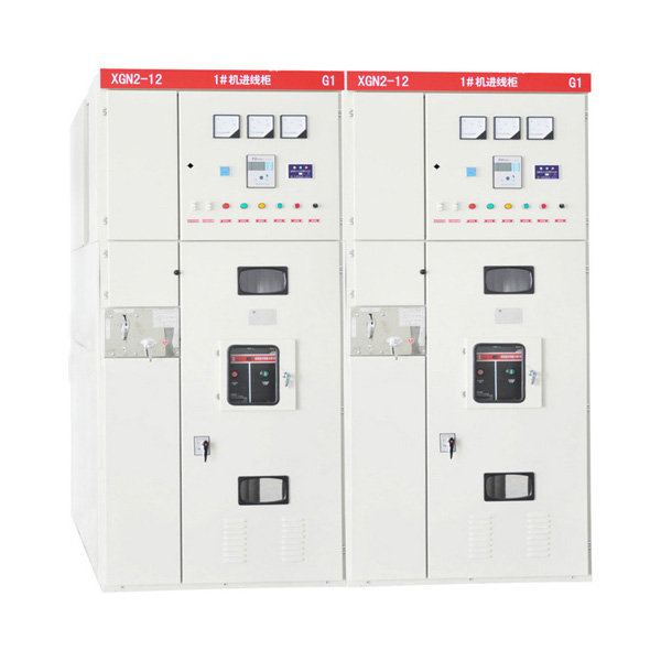
XGN66-12(Z) box-type fixed AC metal-enclosed switchgear (referred to as “switchgear”), this product is suitable for power single busbars with a rated voltage of 3.6-12kv, three-phase AC 50hz, and a rated current of 630A-3150A. Double busbar and single busbar with bypass system are used for receiving and distributing electric energy. It can meet the requirements of various types of power plants, substations (stations) and industrial and mining enterprises.
Performance characteristics:
-
XGN66-12(Z) switchgear is a metal-enclosed box-type structure. The frame of the cabinet is welded by angle steel. The cabinet is divided into a circuit breaker room, a busbar room, a cable room, a relay room, etc., and the rooms are separated by steel plates. open.
-
The circuit breaker room is in the front lower part of the cabinet, the rotation of the circuit breaker is connected with the operating mechanism by the pull rod, the upper terminal of the circuit breaker is connected with the upper isolating switch, the lower terminal of the circuit breaker is connected with the current transformer, and the current transformer is connected with the lower isolating switch The circuit breaker is also equipped with a pressure release channel. If an internal arc occurs, the gas can release the pressure through the exhaust channel.
-
The busbar room is at the rear upper part of the cabinet body. In order to reduce the height of the cabinet body, the busbars are in the shape of a row and supported by qualified insulators with a bending strength of 12kn. The busbars are connected to the busbars of the upper disconnector. isolation.
-
The cable room is behind the lower part of the cabinet. The supporting insulator in the cable room can be equipped with a voltage monitoring device, and the cables are fixed on the bracket. When the main connection line is the connection scheme, this room is the connection room. The relay room is in front of the upper part of the cabinet. Various relays can be installed on the indoor installation board. There are terminal block brackets in the room. Secondary components such as indicating instruments and signal components can be installed on the door. Secondary small busbars can also be arranged on the top.
-
The operating mechanism of the circuit breaker is at the lower left position, and above it is the operation and interlocking mechanism of the isolating switch. The switch cabinet is double-sided maintenance, the secondary components of the relay room are inspected at the front, the operating mechanism, mechanical interlock and transmission part are maintained, and the circuit breaker is inspected. The main busbar and cable terminals are maintained at the back, and lighting lamps are installed in the circuit breaker room. Below the front door, there is a grounding copper bus bar parallel to the cabinet width direction, with a cross-section of 4*40mm².
-
Mechanical interlock: In order to prevent opening and closing of the isolating switch with load, prevent mis-opening and closing of the circuit breaker, prevent mistakenly entering the charged interval, prevent the grounding switch from being charged, and prevent the closing of the switch with a grounding knife, the switch cabinet adopts a corresponding mechanical interlock. The action principle of the interlock is as follows:
Power failure operation (operation-inspection)
The switchgear is in the working position, that is, the upper and lower isolating switches, the circuit breaker is in the closed state, the front and rear doors are locked, and it is in the electric operation. At this time, the small handle is in the working position. First open the circuit breaker, and then pull the small handle to the “break lock” position. At this time, the circuit breaker cannot be closed. Insert the operating handle into the operation hole of the lower isolation and pull it down from top to bottom. Take off the handle, insert it into the operating hole of the upper isolation, pull it down from the top, and pull it to the opening position of the upper isolation, then take down the operating handle, insert it into the operating hole of the grounding switch, and push it from bottom to top, so that the grounding switch is in the closing position. position, at this time, the small handle can be placed in the “inspection” position. The front door can be opened first, and the key behind the door can be taken out to open the back door. After the power failure operation is completed, the maintenance personnel can enter and maintain the circuit breaker room and the cable room.
Transmission operation (overhaul - operation)
If the overhaul is completed and power needs to be transmitted, the operation procedure is as follows: close the back door, take out the key and close the front door, and turn the small handle from the “inspection” position to the “break lock” position. At this time, the front door is locked and the circuit breaker cannot be closed. Insert the operating handle into the operating hole of the grounding switch, pull it from top to bottom, make the grounding switch in the opening position, take down the operating handle, insert it into the operating hole of the upper isolation, and push it from bottom to upper, so that the upper isolation is in the closing position. In the brake position, take down the operating handle, insert it into the operating hole of the lower isolation, push it from bottom to upper, so that the lower isolation is in the closing position, take out the operating handle, and pull the small handle to the working position, then the circuit breaker can be closed .
Normal use conditions:
◆The altitude does not exceed 1000m.
◆Ambient temperature: -25℃~+40℃, the average temperature within 24 hours does not exceed +35℃.
◆The horizontal inclination is not more than 3°C.
◆Seismic intensity does not exceed 8℃.
◆No severe vibration, shock and explosion hazard.
We welcome global agents, distributors, retailers, and other partners to join us and work together to develop mutually beneficial business relationships. Our products have already been well received by customers in many countries and regions, and we look forward to expanding our reach even further.